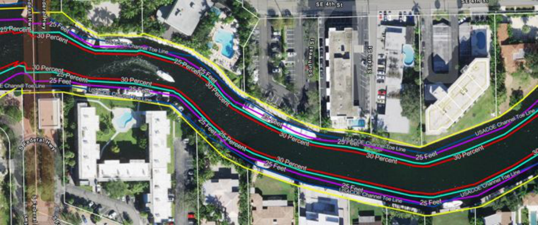
Choke Point 01
Andrews Avenue Crossing
The Andrews Ave bridge crossing is one of the most constrained sections of the navigation corridor. Bridge fenders, the river aligned with almost continuous docked vessels compress the functional river width. This is a high vssel congestion area, even further congested by bridge openings and closing, expecially the railroad bridge .
→ Scroll image horizontally to see full detail
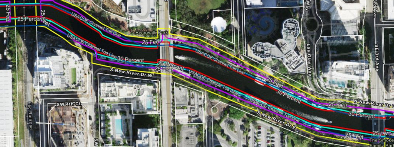
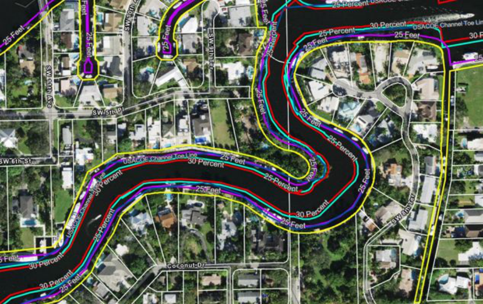
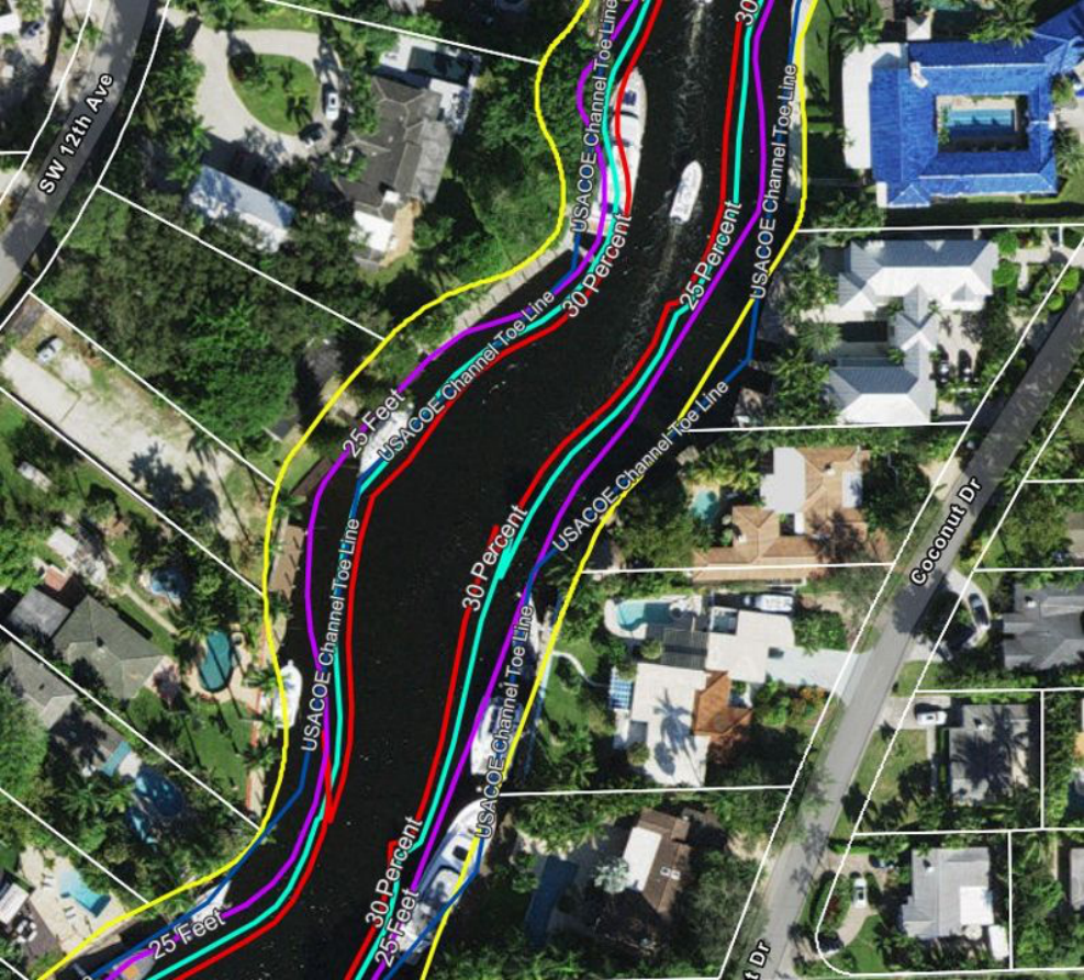
Property line contours (BCPA), measured feet into the channel, 25% and 30% waterway extension limits, and the official USACOE channel toe line. Note: the 30% dock extension limit reaches well into the federally designated channel area.
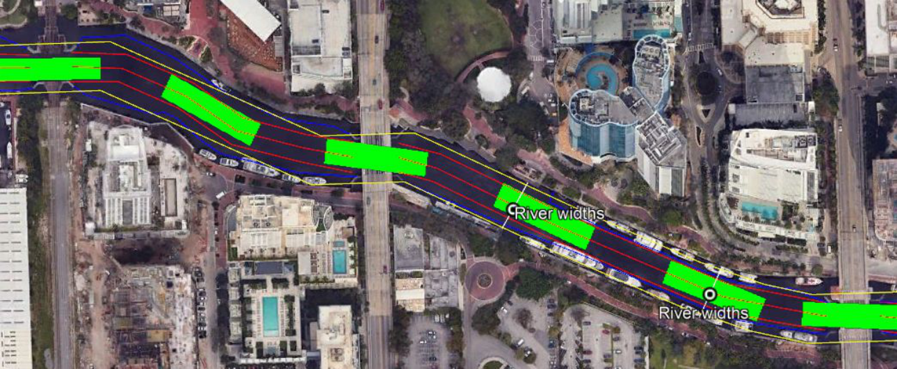
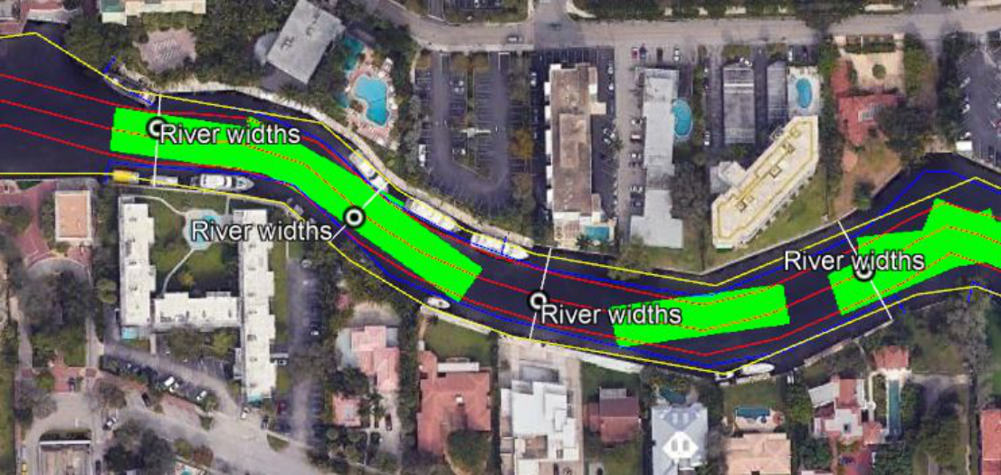
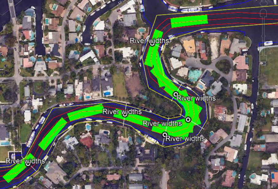
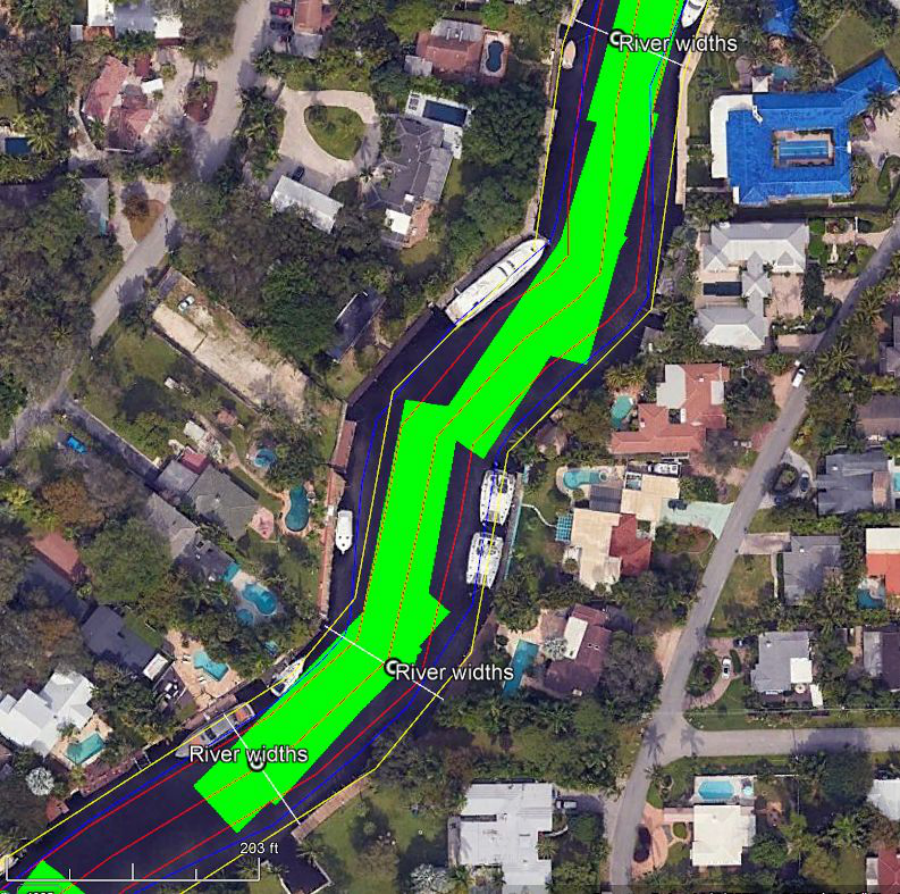
Red corridor: 60-foot minimum navigable channel width. USACOE line: federal channel boundary. Green rectangles: the combined footprint of a 150′ × 50′ barge towed by a 30′ tug on the bow and a 30′ tug on the stern — the absolute minimum physical requirement for a safe utility barge transit.